ASME B16.4:2016 pdf download Gray Iron Threaded Fittings Classes 125 and 250
1 sCOPE
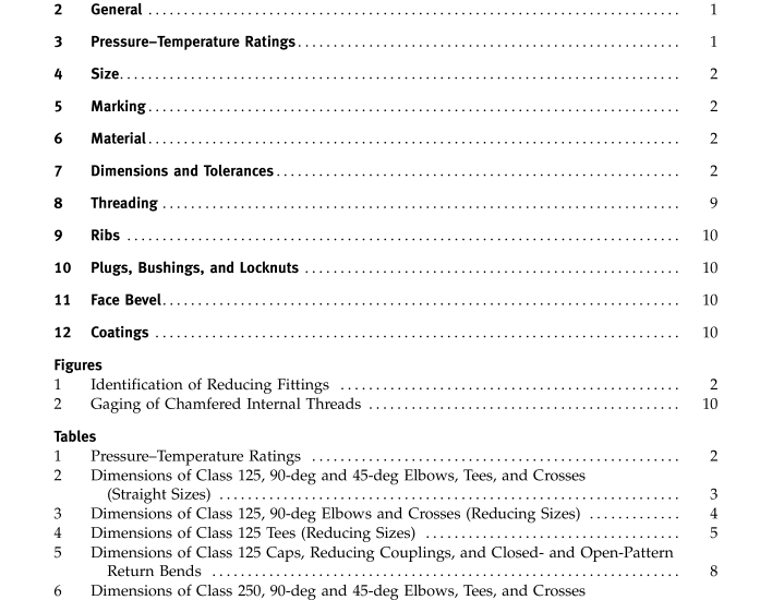
This Standard for gray iron threaded fittings,Classes 125 and 250, covers
a) pressure-temperature ratings
(b) sizes and method of designating openings ofreducing fittings
(c) marking(d) material
(e) dimensions and tolerances(f) threading
ig) coatings
Mandatory Appendix I provides table values inU.S.Customary units.
GENERAL
2.1 References
Standards and specifications adopted by reference inthis Standard are shown in Mandatory Appendix II,which is part of this Standard. It is not considered practi-cal to identify the specific edition of each referencedstandard and specification in the text, when referenced.Instead, the specific editions of the referenced standardsand specifications are listed in Mandatory Appendix II.2.2 Quality Systems
Requirements relating to the product manufacturers’quality systemprogramsare describedinNonmandatory Appendix A.
2.3 Relevant Units
This Standard states values in both SI (Metric) andU.S.Customary units. These systems of units are to beregarded separately as standard. Within the text,theU.S.Customary units are shown in parentheses or inseparate tables that appear in Mandatory Appendix I.The values stated in each system are not exact equiva-lents; therefore, it is required that each system of unitsbe used independently of the other. Combining valuesfrom the two systems constitutes nonconformance withthe Standard.
2.4 Service Conditions
Criteria for selection of materials suitable for particu-lar fluid service are not within the scope of this Standard.
3 PRESSURE–TEMPERATURE RATINGS
(a) Pressure–temperature ratings for these fittings are shown in Tables 1 and I-1.
(b) All ratings are independent of the contained fluid and are the maximum allowable working gage pressures at the tabulated temperatures. Intermediate ratings may be obtained by linear interpolation between the temper- atures shown.
(c) The temperatures shown for the corresponding pressure rating shall be the material temperature of the pressure-retaining structure. It may be assumed that the material temperature is the same as the fluid tempera- ture. Use of a pressure rating at a material temperature other than that of the contained fluid is the responsibilityof the user and subject to the requirements of any appli-cable code.
4SIZE
4.1 Nominal Pipe Size
As applied in this Standard, the use of the phrase”nominal pipe size”or the designation NPS followedby a dimensionless number is for the purpose of identi-fying the end connection of fittings. The number is notnecessarily the same as the fitting inside diameter.4.2 Reducing Fittings
For reducing tees and crosses, the size of the largestrun opening shall be given first, followed by the size ofthe opening at the opposite end of the run. Where thefitting is a tee, the size of the outlet is given last.Wherethe fitting is a cross, the largest side-outlet opening isthe third dimension given, followed by the oppositeopening. The straight-line sketches of Fig. 1 illustratehow the reducing fittings are read.
5MARKING
(a) Each Class 125 fitting shall be marked for identifi-cation with the manufacturer’s name or trademark.(b) Each Class 250 fitting shall be marked for identifi-cation with
( 1) the manufacturer’s name or trademark(2) the numerals “250””
6MATERIAL
Castings shall be produced to meet the requirementsof ASTM A126,Class A,B,or C. The manufacturershall be prepared to certify that the product has been soproduced and that the chemical and physical propertiesthereof, as proved by test specimens,are equal to theserequirements.
